
Bare Fibre PLC Splitters Price in Kenya
Bare PLC Splitter 1x32 in Kenya
KSh 1,000.00
1 available
Continue shoppingBare PLC Splitter 1x32 in Kenya
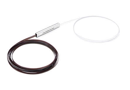
The Bare PLC Splitter 1x32 is a passive fibre optic device designed to divide one incoming single-mode optical signal into 32 separate output fibres. It uses Planar Lightwave Circuit (PLC) technology to distribute optical power evenly across many downstream branches, making it highly suitable for FTTH, GPON, EPON, FTTx and other passive optical network deployments.
Bare 1x32 PLC splitters are designed for installations where compact size and flexible fibre termination are important. Current commercial versions are available with 250 µm G.657A1 single-mode fibre, un-terminated input and output tails, approximately 1.5 m fibre lengths and a 1260–1650 nm operating wavelength range. Corning also manufactures bare splitter platforms using 250 µm G.657.A2 bend-insensitive fibre, demonstrating the widespread use of bend-optimized fibre in compact splitter applications.
At Fiber Optics Kenya, the Bare PLC Splitter 1x32 is an excellent choice for ISPs, FTTH contractors, telecommunications companies and fibre infrastructure projects that need to distribute one feeder fibre across many subscribers while minimizing space inside fibre enclosures. Customers can also source compatible FDB/FAT boxes, ODFs, SC/APC pigtails, splice sleeves, fibre trays, drop cables, fusion-splicing equipment and optical testing tools.
Key Product Specifications
| Specification | Details |
|---|---|
| Product Name | Bare PLC Splitter 1x32 |
| Product Type | Passive Optical PLC Splitter |
| Splitter Configuration | 1 × 32 |
| Number of Inputs | 1 |
| Number of Outputs | 32 |
| Splitting Technology | Planar Lightwave Circuit |
| Typical Split Type | Balanced / Symmetrical |
| Ideal Optical Share per Output | Approx. 3.125% |
| Fibre Mode | Single Mode |
| Typical Fibre Category | OS2 |
| Common Fibre Types | G.657A1 / G.657A2 / G.652D depending on model |
| Typical Bare Fibre Diameter | 250 µm |
| Connector Type | None on bare version |
| Typical Fibre Length | Approx. 1.5 m depending on model |
| Operating Wavelength | 1260–1650 nm |
| Theoretical Splitting Loss | Approx. 15.05 dB |
| Typical Practical Insertion Loss | Approx. 16.2–17.5 dB depending on product grade |
| Typical Directivity | ≥55 dB on representative products |
| Typical PDL | Around ≤0.3 dB depending on model |
| Package Style | Bare Fibre / Compact Steel Tube |
| Power Requirement | None |
| Primary Applications | FTTH, GPON, EPON, FTTx, FDB, ODF |
| Professional Installation | Available |
| Delivery | Available throughout Kenya |
A current 1x32 commercial splitter specification lists 1260–1650 nm operation, G.657A1/G.652D fibre and typical insertion loss around 16.2 dB, while other commercial products specify approximately 16.5–17 dB depending on grade and construction.
What Does Bare PLC Splitter 1x32 Mean?
| Term | Meaning |
|---|---|
| PLC | Planar Lightwave Circuit |
| 1x32 | One optical input divided into 32 outputs |
| Bare | Fibre leads supplied without connectors |
| Splitter | Device that divides optical power |
| Single Mode | Fibre optimized for long-distance optical transmission |
| 250 µm | Common coating diameter of bare fibre |
| FTTH | Fibre to the Home |
| PON | Passive Optical Network |
| Balanced | Approximately equal power across outputs |
The splitter is completely passive, so it does not require electrical power, software configuration or network management.
How a 1x32 PLC Splitter Works
The incoming optical signal enters one fibre and passes through a planar optical waveguide that divides the signal into 32 output paths.
| Stage | Function |
|---|---|
| Input Fibre | Receives incoming optical power |
| PLC Optical Circuit | Divides optical signal |
| Output Fibres 1–8 | Carry split optical power |
| Output Fibres 9–16 | Carry split optical power |
| Output Fibres 17–24 | Carry split optical power |
| Output Fibres 25–32 | Carry split optical power |
An ideal 1x32 split introduces approximately 15.05 dB of theoretical splitting loss because the incoming optical power is shared across 32 outputs. Real PLC splitter insertion loss is higher because of excess device loss and manufacturing tolerances.
Typical 1x32 Optical Distribution
| Parameter | Value |
|---|---|
| Input Fibres | 1 |
| Output Fibres | 32 |
| Ideal Power per Output | 3.125% |
| Theoretical Split Loss | ~15.05 dB |
| Practical Insertion Loss | Typically ~16–17.5 dB |
| Electrical Power Required | None |
This makes a 1x32 splitter particularly useful when one feeder fibre needs to serve a relatively large subscriber group.
PLC Splitter Technology
PLC splitters use silica-based planar optical circuits to provide scalable optical power distribution.
| PLC Feature | Benefit |
|---|---|
| High Split Ratios | Supports many subscribers |
| Wide Wavelength Range | Compatible with multiple PON services |
| Balanced Outputs | Similar power across channels |
| Low PDL | Stable optical characteristics |
| Compact Construction | Fits inside fibre enclosures |
| Passive Operation | No electricity required |
| High Reliability | Suitable for carrier networks |
| Scalable Deployment | Available from 1x2 to 1x64 and beyond |
Commercial PLC splitter ranges commonly include 1x2, 1x4, 1x8, 1x16, 1x32 and 1x64 configurations.
Typical Optical Performance
| Optical Parameter | Typical / Representative Value |
|---|---|
| Configuration | 1x32 |
| Operating Wavelength | 1260–1650 nm |
| Typical Fibre Type | G.657A1 / G.652D |
| Typical Insertion Loss | ≤16.2–17.5 dB depending on model |
| Theoretical Split Loss | ~15.05 dB |
| Polarization Dependent Loss | Around ≤0.3 dB on representative products |
| Directivity | ≥55 dB |
| Return Loss | Product/termination dependent |
| Fibre Diameter | 250 µm commonly |
| Fibre Mode | Single Mode |
One documented 1x32 PLC splitter lists 16.2 dB typical and 17.1 dB maximum insertion loss, ≥55 dB directivity and ≤0.3 dB PDL.
Why the 1260–1650 nm Range Matters
The broad PLC operating window allows the same splitter to pass wavelengths used by several generations of passive optical networking.
| Wavelength | Typical Application |
|---|---|
| 1310 nm | Upstream PON transmission |
| 1490 nm | GPON downstream |
| 1550 nm | Video overlay / optical services |
| 1577 nm | Newer downstream PON technologies |
| 1625 nm | Testing and network monitoring |
Commercial 1x32 bare splitters are specifically offered with a 1260–1650 nm operating specification.
G.657A1 Single Mode Fibre
Many bare PLC splitters use G.657A1 bend-insensitive fibre because they must fit into compact fibre-management systems.
| G.657A1 Feature | Benefit |
|---|---|
| Single Mode | Suitable for long optical links |
| Bend Insensitive | Better performance around tight routing |
| Compact Enclosure Use | Excellent |
| FTTH Deployment | Excellent |
| Splice Tray Routing | Excellent |
| FDB Installation | Excellent |
| PON Compatibility | Excellent |
Exact commercial 1x32 splitter products are available using 250 µm G.657A1 single-mode OS2 fibre.
G.657A1 vs G.657A2 Fibre
| Feature | G.657A1 | G.657A2 |
|---|---|---|
| Fibre Mode | Single Mode | Single Mode |
| Bend Insensitive | Yes | Yes |
| Bend Performance | Excellent | Enhanced |
| FTTH Networks | Excellent | Excellent |
| Compact Splitter Routing | Excellent | Excellent |
| Splice Tray Use | Excellent | Excellent |
Corning states that its bare splitter products use 250 µm G.657.A2 low-bend-loss fibre, while many commercial bare 1x32 products use G.657A1.
Bare Fibre Construction
A major advantage of the bare splitter format is that the fibres remain unconnectorized.
| Bare Fibre Feature | Benefit |
|---|---|
| No Factory Connectors | Flexible final termination |
| 250 µm Leads | Minimal enclosure space |
| Fusion-Splice Ready | Direct network integration |
| Compact Steel Tube | Protects PLC optical circuit |
| Custom Connector Choice | APC, UPC or direct splice |
| Colour-Coded Outputs | Easier channel identification |
| Lower Physical Bulk | Useful in high-density enclosures |
A current 1x32 product is supplied with 1.5 m, 250 µm bare input and output legs with no connectors.
Typical Physical Construction
| Component | Function |
|---|---|
| Single Input Fibre | Carries feeder optical signal |
| PLC Waveguide Chip | Divides optical power |
| Steel Protection Tube | Protects internal circuit |
| 32 Output Fibres | Carry downstream optical signals |
| 250 µm Fibre Coating | Protects glass |
| Output Identification | Helps distinguish all 32 fibres |
Because 250 µm fibres have limited mechanical protection, they should be kept inside an appropriate ODF, FDB, splice tray or protected enclosure.
Bare PLC Splitter vs Mini PLC Splitter
| Feature | Bare 1x32 PLC | Mini / Blockless 1x32 PLC |
|---|---|---|
| Overall Size | Very Compact | Compact |
| Typical Fibre Leads | 250 µm | 900 µm commonly |
| Mechanical Protection | Lower | Higher |
| Connector Options | Usually None | Available |
| Splice Tray Integration | Excellent | Excellent |
| FDB Installation | Excellent | Excellent |
| Handling Strength | Lower | Better |
Bare PLC Splitter vs ABS Box Splitter
| Feature | Bare 1x32 | ABS Box 1x32 |
|---|---|---|
| Size | Very Small | Larger |
| Mechanical Protection | Minimal | High |
| Unconnectorized Leads | Common | Optional |
| Connectorized Options | Less common | Very Common |
| Splice Tray Use | Excellent | Less compact |
| Rack/Cabinet Use | Requires enclosure | Excellent |
| Customization | High | Moderate |
1x8 vs 1x16 vs 1x32 PLC Splitter
| Feature | 1x8 | 1x16 | 1x32 |
|---|---|---|---|
| Outputs | 8 | 16 | 32 |
| Ideal Power per Output | 12.5% | 6.25% | 3.125% |
| Theoretical Split Loss | ~9.03 dB | ~12.04 dB | ~15.05 dB |
| Typical Practical Loss | ~10–11 dB | ~13–14.5 dB | ~16–17.5 dB |
| Subscriber Capacity | 8 | 16 | 32 |
| Optical Budget Requirement | Moderate | Higher | High |
| FTTH Distribution | Excellent | Excellent | Excellent |
As split ratio increases, subscriber capacity increases but the optical power available to each output decreases.
1x32 vs 1x64 PLC Splitter
| Feature | 1x32 | 1x64 |
|---|---|---|
| Outputs | 32 | 64 |
| Ideal Power per Output | 3.125% | 1.5625% |
| Theoretical Split Loss | ~15.05 dB | ~18.06 dB |
| Optical Budget Requirement | High | Higher |
| Subscriber Density | High | Very High |
| Typical FTTH Use | Very Common | Network dependent |
| Installation Complexity | High | Higher |
Why Choose a 1x32 Split Ratio?

A 1x32 splitter is a popular choice where fibre operators need substantial subscriber capacity while keeping optical loss within the available PON budget.
| Deployment | Benefit |
|---|---|
| Apartment Building | Serve multiple homes |
| Residential Estate | High subscriber density |
| Office Complex | Multiple fibre endpoints |
| Campus Network | Large downstream branch count |
| ISP FTTH Network | Efficient feeder utilization |
| FDB / FAT Deployment | High-density distribution |
| Urban Fibre Network | Reduces feeder fibre requirement |
Balanced 1x32 PLC Splitter
Most standard PLC splitters are balanced, meaning the optical power is designed to be distributed approximately equally across all outputs.
| Parameter | Balanced 1x32 |
|---|---|
| Inputs | 1 |
| Outputs | 32 |
| Ideal Share per Output | 3.125% |
| Output Distribution | Approximately Equal |
| PON Suitability | Excellent |
| FTTH Suitability | Excellent |
Cascaded PLC Splitting
A 1x32 splitter may be used as a single-stage splitter or as part of a cascaded network.
| Example Splitter Design | Potential Outputs |
|---|---|
| 1x2 → 1x16 | 32 |
| 1x4 → 1x8 | 32 |
| 1x8 → 1x4 | 32 |
| Single 1x32 | 32 |
A single 1x32 configuration can simplify network topology, while cascaded splitting may offer more flexibility in geographically distributed networks. In both cases, the entire splitter loss must be incorporated into the PON optical budget.
Optical Budget Considerations
| Loss Source | Must Be Calculated? |
|---|---|
| 1x32 PLC Splitter | Yes |
| Feeder Fibre Loss | Yes |
| Distribution Fibre Loss | Yes |
| Drop Fibre Loss | Yes |
| Fusion Splices | Yes |
| Connector Pairs | Yes |
| Adapters | Yes |
| Additional Splitters | Yes |
| Engineering Margin | Yes |
A 1x32 PLC splitter alone can contribute roughly 16–17.5 dB of insertion loss, making optical-budget planning particularly important.
Key Benefits of Bare PLC Splitter 1x32
High Subscriber Capacity
One feeder fibre can provide 32 downstream optical paths.
Compact Installation
The bare 250 µm design minimizes space requirements inside distribution boxes and splice trays.
Wide Wavelength Range
Commercial products operate across 1260–1650 nm, supporting multiple PON technologies.
Bend-Insensitive Fibre Options
G.657A1 and G.657A2 fibre options improve routing inside compact fibre enclosures.
No Electrical Power Required
The splitter is completely passive.
Flexible Termination
Bare leads can be fusion-spliced directly to distribution fibres or connectorized pigtails.
Reduced Feeder Fibre Requirement
A single optical feeder can support many downstream subscriber connections.
Watch Bare PLC Splitter 1x32
Watch on YouTube: https://youtu.be/z6ueLVVllUU
The Bare PLC Splitter 1x32 provides a high-density method of distributing one incoming optical fibre across 32 downstream paths while using no powered network equipment. Exact commercial products are available with 250 µm G.657A1 single-mode OS2 fibre, un-terminated tails, approximately 1.5 m lead lengths and 1260–1650 nm operation, making the splitter especially suitable for compact FTTH distribution infrastructure.
With 32 outputs, each channel receives approximately 3.125% of the incoming optical power in an ideal split. This creates a theoretical splitting loss of roughly 15.05 dB, while real devices typically introduce approximately 16–17.5 dB depending on product grade. Because this loss is substantial, installers must calculate the full link budget—including fibre attenuation, splices, adapters and connector losses—before deploying a 1x32 splitter.
The bare configuration gives installers greater flexibility because the 32 output fibres can be fusion-spliced directly into the required distribution architecture. Fiber Optics Kenya can supply the Bare PLC Splitter 1x32 together with SC/APC pigtails, fusion splice sleeves, FDB/FAT boxes, ODFs, FTTH drop cables, fibre cleavers, fusion-splicing equipment and optical testing tools, allowing installers to source complete passive optical distribution solutions.
Applications of Bare PLC Splitter 1x32
1. FTTH Networks
Distribute one feeder fibre to as many as 32 subscriber or downstream branches, subject to network design.
2. GPON Networks
Provide passive optical distribution between an OLT and multiple ONTs.
3. EPON Networks
Support one-to-many optical signal distribution without active switches.
4. Fibre Distribution Boxes
Install the compact splitter inside high-capacity FDBs.
5. FAT Boxes
Provide up to 32 optical distribution branches from a feeder connection.
6. Optical Distribution Frames
Integrate the splitter into structured ODF fibre-management systems.
7. Fibre Joint Closures
Fusion-splice bare splitter leads directly into outside-plant networks.
8. Residential Estates
Serve larger clusters of subscriber fibre connections.
9. Commercial Buildings
Distribute optical services to multiple floors, offices or units.
10. Telecommunications Networks
Provide passive high-density fibre distribution without electrical equipment.
Typical FTTH Network Using Bare PLC Splitter 1x32
| Network Stage | Typical Component |
|---|---|
| Central Equipment | OLT |
| Feeder Fibre | Single Mode |
| Splitter Input | 1 Fibre |
| Splitter | Bare PLC Splitter 1x32 |
| Output Fibres | 32 |
| Distribution Enclosure | FDB / FAT |
| Subscriber Fibre | FTTH Drop Cable |
| Subscriber Equipment | ONT / ONU |
Installation Considerations
| Installation Factor | Recommendation |
|---|---|
| Optical Power Budget | Calculate carefully before deployment |
| Bare Fibre Protection | Install inside proper enclosure |
| Fibre Identification | Label all 32 outputs |
| Minimum Bend Radius | Follow fibre specification |
| Splice Protection | Use quality splice sleeves |
| Fibre Management | Use suitable high-capacity splice trays |
| Connector Cleanliness | Clean all terminated interfaces |
| Output Testing | Verify every output |
| Engineering Margin | Leave adequate optical margin |
| Future Maintenance | Keep fibres well documented |
Recommended Accessories
| Accessory | Purpose |
|---|---|
| SC/APC Pigtails | Terminate bare splitter outputs |
| SC/UPC Pigtails | UPC termination where required |
| Fusion Splice Sleeves | Protect optical joints |
| High-Capacity Splice Tray | Organize 32 output fibres |
| FDB / FAT Box | Houses splitter and distribution fibres |
| Optical Distribution Frame | Structured fibre management |
| FTTH Drop Cable | Subscriber fibre connection |
| Fibre Cleaver | Precision fibre preparation |
| Fibre Stripper | Removes fibre coating |
| Fusion Splicer | Joins bare splitter fibres |
| Optical Power Meter | Measures signal levels |
| PON Power Meter | Tests PON wavelengths |
| Visual Fault Locator | Assists fibre identification |
| OTDR | Tests completed fibre links |
Why Buy Bare PLC Splitter 1x32 from Fiber Optics Kenya?
| Why Choose Fiber Optics Kenya? | Customer Benefit |
|---|---|
| 1x32 PLC Splitters | High-density optical distribution |
| Bare Fibre Options | Compact installation |
| OS2 Single Mode Solutions | Suitable for FTTH and PON |
| G.657 Fibre Options | Better bend performance |
| SC/APC Pigtails | Matching termination products |
| FDB & FAT Boxes | Complete distribution solutions |
| ODFs & Splice Trays | Professional fibre management |
| FTTH Drop Cables | Complete subscriber connections |
| Fusion Splicing Tools | Installation equipment available |
| Testing Equipment | Verify network performance |
| Technical Guidance | Help with split ratios and optical budgets |
| Bulk Supply | Suitable for ISPs and contractors |
| Competitive Pricing | Cost-effective network deployment |
| Nationwide Delivery | Supply throughout Kenya |
Frequently Asked Questions
What is a Bare PLC Splitter 1x32?
It is a passive fibre optic splitter with one input and 32 output fibres, normally supplied without connectors for fusion-splice installation.
What does PLC mean?
PLC means Planar Lightwave Circuit.
What does 1x32 mean?
It means the splitter has one optical input and 32 optical outputs.
How much optical power does each output receive?
In an ideal equal split, each output receives approximately 3.125% of the incoming optical power.
What is the theoretical loss of a 1x32 splitter?
The theoretical splitting loss is approximately 15.05 dB.
What is the actual insertion loss?
Commercial 1x32 PLC splitters commonly specify approximately 16.2–17.5 dB, depending on product quality, design and packaging.
What fibre type is commonly used?
Commercial bare 1x32 products are available using G.657A1 single-mode OS2 fibre.
Is G.657A2 available?
Yes. Corning's bare splitter platform uses 250 µm G.657.A2 low-bend-loss fibre.
What fibre diameter is commonly used?
Bare splitter products commonly use 250 µm fibre.
Does it come with connectors?
A true bare-fibre model normally comes un-terminated without connectors.
How long are the fibre leads?
One current 1x32 product uses 1.5 m input and output legs.
What is the operating wavelength?
Current 1x32 bare products commonly specify 1260–1650 nm.
Does it require electrical power?
No. PLC splitters are completely passive optical components.
Does it require fusion splicing?
Bare models usually require fusion splicing because the fibre tails are not connectorized.
Can it be used for FTTH?
Yes. Bare 1x32 splitters are used in FTTH and FTTx optical distribution systems.
Can it be used in GPON?
Yes. GPON is one of the principal applications of PLC splitting technology.
Can it be used in EPON?
Yes. 1x32 PLC splitters are suitable for EPON and other passive optical network architectures.
Can one 1x32 splitter serve 32 subscribers?
Potentially yes. Each output can serve an individual subscriber or downstream branch, provided the overall network architecture and optical power budget support it.
Can a 1x32 splitter be cascaded?
Yes, but cascading adds further optical loss. The combined loss of every splitter, connector, splice and fibre segment must remain within the PON optical budget.
Is 1x32 better than 1x16?
It provides twice as many outputs but introduces greater splitting loss. The correct choice depends on subscriber density and available optical power budget.
What is the difference between 1x32 and 1x64?
A 1x64 splitter supports twice as many outputs but also introduces roughly another 3 dB of theoretical splitting loss.
Can it be installed in an FDB?
Yes. Bare PLC splitters are particularly suitable for integration into fibre distribution enclosures.
Can it be installed in an ODF?
Yes. It can be installed in an ODF or high-capacity splice tray with adequate fibre management.
Can I terminate the outputs with SC/APC?
Yes. Bare output fibres can be fusion-spliced to SC/APC pigtails when APC termination is required.
Do you supply SC/APC pigtails?
Yes. Fiber Optics Kenya can supply compatible SC/APC single-mode pigtails.
Do you supply FDB and FAT boxes?
Yes. Compatible fibre distribution boxes and access terminals can be supplied.
Do you supply ODFs and splice trays?
Yes. ODFs, splice trays and other fibre-management equipment can be supplied.
Do you supply fusion-splicing equipment?
Yes. Fibre cleavers, strippers, fusion splicers and related installation tools can be supplied.
Do you provide fibre installation and testing?
Yes. Professional fibre splicing, installation, termination and optical testing support is available.
Do you deliver outside Nairobi?
Yes. Fiber Optics Kenya supplies fibre optic products and accessories throughout Kenya.
Contact Fiber Optics Kenya
Fiber Optics Kenya
Lyric House
7th Floor Room S9
Kimathi Street
Nairobi
Phone: +254 704 991 492
Email: info@fibreopticskenya.co.ke
The Bare PLC Splitter 1x32 provides compact, high-density optical distribution for FTTH, GPON, EPON and other passive fibre networks serving multiple subscribers.
Contact Fiber Optics Kenya for competitive pricing, PLC splitters, FDBs, ODFs, termination accessories, bulk orders and nationwide delivery across Kenya.